6/ Specifications
|
Printing |
Thermal dot matrix (serial non-impact) |
|
Print operation |
Continuous |
|
Characters |
ASCII 95
|
|
Character matrices |
Normal 5 X 7 |
|
Character size |
Normal 1.8 mm
(.0708”) (W) x 2.4mm (.0944”)
(H) |
|
Characters per line |
Normal 32 |
|
Character spacing |
Elongated 16 |
|
Line spacing |
4.23 mm (1/6”) |
|
Printing speed |
Normal 30
characters/sec |
|
Paper |
105+0/-1 mm (4-1/8”) wide thermal paper (26-1332) |
|
Interface |
Serial interface |
|
Dimensions |
210 mm (W) X 150 mm (L) x 80mm(H) (8-9/32” x 5-29/32” x 3-5/32”) |
|
Weight |
1.5 kg (3.3 lbs) approx. |
|
Power supply |
120 V AC, 60Hz (220/240 V, 50Hz for the units purchased in Europe/Australia) 18 W max. |
Environmental (Operating and Storage)
Input Voltage: ± 12.5% of rated voltage (± 10% for European and Australian models)
Temperature and Humidity Durability:
|
Operating Conditions: |
+5°C (+41°F) to 40°C (104°F) |
|
Storage Conditions: |
-40°C (-40°F) to 71°C (1 60°F) |
Interface Specifications
Communication Method
This interface receives serial, asynchronous ASCII data.
Signal Pin Assignment
| Pin No. | Name |  |
|
| 1 | NC | ||
| 2 | STATUS | ||
| 3 | GND | ||
| 4 | DATA |
Interface Lines Description
1. DATA (Pin No.4)
Direction — To Printer.
Signals on this circuit are generated by the Computer for transmission of data
to the Printer.
2. STATUS (Pin No.2)
Direction — To Computer
This signal indicates to the computer whether or not the Printer can accept
data. The OFF condition (LOW) indicates that the Printer is BUSY and cannot
accept any more data. The ON condition (HIGH) indicates the printer is NOT BUSY,
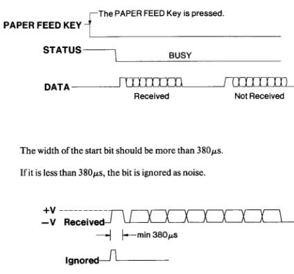
and can accept more data from the Computer. This line goes LOW (BUSY) while:
- One-code ASCII data is received.
- Power-up is initialized.
- The PAPER FEED Key is pressed and data is received.
- Paper is jammed so that the Printer cannot shift the print head.
- Executing the Self Test Printing.
3. GROUND (Pin No.3)
This signal wire establishes a common ground between the Printer and the Computer.
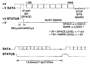
Data Format
1 START BIT + 8 DATA BITS +2 STOP BITS no parity bit.
Baud Rate
600 Baud only.
Timing Chart
|
|